Floor Flatness for AGVs and AMRs
Floor Flatness for AGVs and AMRs
A performance-based approach to specification measurement and rectification
PCE Vietnam Technical Article
An AGV or AMR does not experience a warehouse floor as a conventional slab. It experiences a continuous sequence of slopes, elevation changes, joints and local irregularities through a particular wheel arrangement. Floor flatness therefore influences stability, traction, sensor performance, load control, travel speed, maintenance demand and the reliability of the overall automation system.
PCE Vietnam recommends a performance-based approach that distinguishes between areas of random movement and areas of defined movement, applies suitable profile-based properties, and uses continuous measurement to identify the floor characteristics that affect robot operation. The criteria presented in this article provide a practical guideline for AGV and AMR floors, but they should not be applied as one universal specification for every project. The optimum requirement depends on the actual AGV or AMR selected, its geometry, operating speed, payload, wheel system, control strategy and travel environment. The specific vehicle type and operating conditions should therefore be confirmed before the floor specification is finalized.
The floor is part of the automation system
Traditional floor acceptance often focuses on the slab as a construction element. Automation changes the perspective. A robot with small, hard wheels may react strongly to short-wavelength irregularities that would be insignificant to a forklift. A vehicle carrying a tall or sensitive load may require tighter control than a low-profile unit. A robot that travels repeatedly along fixed wheel tracks creates a different measurement problem from an AMR that can approach a workstation from any direction.
For this reason, a specification should describe the surface characteristics that affect the vehicle, at the spatial intervals and directions that matter to its wheelbase and track width. A single global flatness number cannot fully represent these interactions. The measurement method must reproduce, as closely as practical, the way the selected robot engages with the floor.
Two operating zones require different assessment strategies
PCE Vietnam separates the operating floor into two functional zones. This distinction is central to an efficient inspection plan because each zone requires a different sampling logic and set of performance properties.
Random movement areas

Areas outside racking may include open travel zones, intersections, workstations, charging locations and maintenance areas. Robots can approach these locations from several directions, so a single longitudinal survey line is not enough. Where travel paths are not known, PCE Vietnam recommends measurement on a 1 m grid.
For these areas, PCE Vietnam applies continuous profile assessment along robot travel paths and evaluates deviation from mean lines of 1.0 m, 2.0 m and 4.0 m. As a general guideline, the corresponding limits are less than 2.0 mm, 3.0 mm and 5.0 mm. This multi-length approach identifies surface variation at more than one wavelength.
Defined movement areas

Inside racking or other constrained routes, the robot follows repeatable wheel tracks. PCE Vietnam therefore applies a defined-movement assessment based on four properties: dZ, the elevation difference between the centres of the front wheels; dX, the elevation difference between the centre of the front axle and the centre of the rear axle; and d²Z and d²X, the changes in those transverse and longitudinal values over the stated assessment interval.
These properties represent transverse attitude, longitudinal attitude and the rate at which each changes. As a general selection basis, DM1, DM2 and DM3 classifications correspond to rack top-beam heights above 13 m, from 8 m to 13 m, and up to 8 m. All four defined-movement properties should comply at every assessed location. Non-compliant positions should be accurately marked so that any grinding is targeted from measured evidence rather than visual judgement.
Measurement resolution matters
PCE Vietnam requires specialized equipment with 0.1 mm measurement accuracy and a rolling profileograph that collects data continuously at 50 mm intervals. Widely spaced spot levels may miss local humps, depressions and abrupt changes near joints. Continuous profile data also supports graphs, limit checks and precise setting-out for corrective grinding. The equipment and data-collection approach should be consistent with the profile-based measurement principles applied under DIN 15185 and TR34 4th Edition, as relevant to the selected assessment.
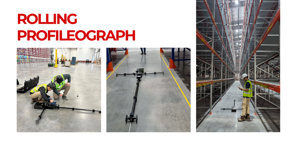
The selected equipment should be configured for the assessment property being reported. In defined routes, the measurement geometry must correspond to the robot wheel tracks or to a justified simulation of the vehicle geometry. In random-traffic zones, the survey pattern must provide adequate directional coverage. Measurement accuracy, repeatability, calibration, reporting resolution and traceability should be stated in the inspection plan.
Why the final tolerance must be robot specific
The general criteria presented above provide a practical starting point for the design, tendering and quality control of AGV and AMR floors. Nevertheless, two robots operating in the same building may respond differently to the same floor profile. Applying generic limits without checking the selected platform can produce either an unnecessarily expensive floor or a floor that passes the written requirement but does not support reliable operation.
| Robot or operating input | Why it affects the floor specification |
| Wheel track and wheelbase | Determine the transverse and longitudinal distances over which elevation differences should be assessed. |
| Wheel diameter and material | Influence sensitivity to short-wavelength irregularities, joint edges and surface texture. |
| Number and arrangement of wheels | Affect load sharing, and the most representative measurement geometry. |
| Travel speed and acceleration | Higher dynamic demand may require tighter control than slow commissioning or nominal travel. |
| Navigation and control system | May be affected by vibration, wheel slip, encoder error, sensor height variation or loss of positioning quality. |
| Route definition and traffic density | Determine whether wheel-track surveys, multidirectional grids or a combination is required. |
| Joints and transitions | Require separate attention because a floor can satisfy general profile limits while a joint still creates impact or wheel disturbance. |
A performance based specification process
A robust specification should be developed before slab construction or, for an existing facility, before rectification is priced. PCE Vietnam recommends the following sequence.
- Define the automation duty. Confirm the vehicle model, load cases, operating speeds, route map, rack interfaces, workstations, charging areas and critical transitions.
- Obtain manufacturer limits. Request the AGV or AMR supplier’s allowable floor slopes, steps, gaps, joints, local unevenness, traction and surface-condition requirements, including the test method behind each value.
- Translate the vehicle into measurement geometry. Use the wheel track, wheelbase, wheel arrangement and direction of travel to select the relevant transverse, longitudinal and change-of-slope properties.
- Classify the operating zones. Separate defined routes from random-traffic areas and identify locations needing additional checks, such as ramps, joints, transfer stations and charging points.
- Set acceptance criteria and coverage. State the limits, compliance rule, sampling interval, grid or wheel-track layout, treatment of joints, survey direction, instrument capability and reporting method.
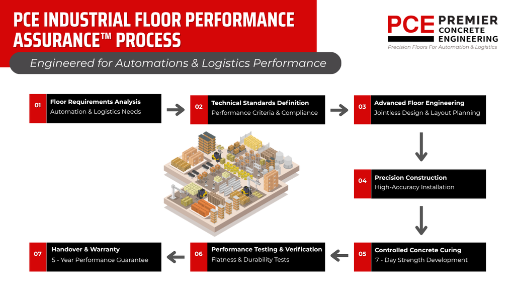
- Measure and rectify from data. Use continuous profiles and graphical reporting to locate non-compliance, design targeted grinding or repair, and verify the corrected floor using the same assessment basis.
Specifying enough without overspecifying
Tighter tolerances are not automatically better. They can increase construction difficulty, survey scope, grinding volume, programme risk and cost. Conversely, a broad generic requirement may fail to control the particular floor wavelengths or local features that affect the robot. The objective is a technically justified acceptance envelope: stringent where the vehicle and operation require it, and practical where additional precision would not improve performance.
This is especially important when several vehicle types will share a facility. The governing criteria may come from the most sensitive vehicle in each zone rather than from one building-wide classification.
The role of PCE Vietnam
PCE Vietnam can review the proposed AGV or AMR platform and convert its operational requirements into a project-specific floor specification and inspection plan. This includes selecting appropriate properties and limits, defining survey coverage, checking instrument suitability, assessing existing floors, reporting non-compliance, preparing targeted rectification advice and verifying completed work.
The general requirements in this article provide a strong basis for discussion among owners, automation suppliers, designers, contractors and floor specialists. The final project specification, however, should be confirmed against the specific robot and its intended operation. That step aligns the concrete floor with the actual automation system and directs quality-control effort to the surface characteristics that matter most.